- Home
- About Us
- Join/Renew
- Member Benefits
- Member Pages
- Log In
- Help
- Museum Store
Freeze and install the cones for the bull gear carrier from the interior of the case and the removable side plate.
Next, take the top of the bull gear and tilt it and install, top first, in the case. Slide the bottom in and engage with the worm gear.
As a general note, always chase all threads.
Install the loose carrier plate with bearing cone and bolt it down. Check to see if the assembly will rotate. I used a socket on the rear castle nut.
Screw in the bearing adjustment sleeves until they contact the bearing cups. Check for rotation again. Then tighten the adjusters one turn a side, using a square shafted screwdriver. Check rotation and side play.
The object is to remove the side play and locate the bull bear over the worm gear with little backlash.
Initially, I had some binding in the gears. I had to tighten one side and loosen the other (which moves the carrier from right to left) until the binding went away, side play was minimized and the backlash felt acceptable.
I got it so it really runs smooth with no binding or excess play. Next I will check tooth contact when I can get some Prussian blue. You can view the teeth through the large hole in the rear of the case.
I have seen a bull gear failure on a Stutz, as the clearance changed when the rear got hot and it chewed it’s self apart. Do you have a factory side and end play figure? Also, correct lubricant is a must with that bronze bull gear. What’s the ratio of your set?
Edgar,
Ratio is 4.43 to 1. I have no specs. Would love to find some. I was going to use API GL-4, 140 weight.
Let me know if I lost my mind somewhere.
Thanks for the help.
Bill
Edgar,
Greg pointed out this was a bad ratio. I misread the stamp. It is 4 2/7 or 4.28.
Bill
I am not too familiar with these worm drive rears, but it seems many that are set up “correctly” tend to come apart. Not sure if it is the new high speed gears, or a material / process of the gear cutting, or set up issue. Does anyone have any factory or Timken set up info on these that can be published here?
Edgar,
All the gears in this rear end are original Pierce so there isn’t a manufacturing spec issue. Preload and backlash spec would be great if some one can find some. I have some from about 1919,that show tooth pattern but things change a lot in 14 years.
The only adjustments I see are right to left and preload on the bull gear and front to back on the worm.
Thanks for your help.
Bill
Hi Bill,
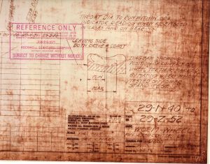
Glad to see you’re getting the parts together. I checked my Timken drawings and found the specs for backlash, and a picture of the contact pattern “when tested on power stand test”. Contact pattern in this post, backlash in next.
Bob

Bill,
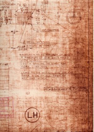
Here is the backlash photo (0.010 to 0.018″)
Bob”

Bob,
First off, thank you again for coming to the worm drive’s rescue and secondly, it is amazing that you have that print. It has everything I was looking for. It also proves how simple the worm drives were. No pinion depth, etc.
Thanks again.
Bill
Bob, I am impressed! I can see your big smile as you posted the info……thanks, Ed.
This is a little out of sequence as you should check tooth pattern and backlash first, but while I was waiting for the USPS to deliver my tube of Prussian Blue and magnetic dial indicator setup I thought I would cover 2 additional steps.
Once you have things in spec, you need to lock down the bearing adjustment rings on both sides of the carrier. The white (painted for clarity) tips have to be aligned so that the retaining plate (right) fits on the single lower post, the 2 upper posts and the bolt holes line up.
This is a little fiddly and I used a small hammer and a flat bladed screwdriver to tap everything in place. These should be only minor adjustments and I recommend tightening instead of loosening the rings. If you move them too much you can destroy your clearances.
Once aligned, insert plate and bolt it down with the 2 drilled head bolts. Install safety wire, I like figure 8’s, and twist the ends, preferably with an aircraft safety wire pliers. Mine got up and walked away at some time in the past.
Repeat on the other side. Note: be sure to run nuts down all studs on the removable side and tighten the plate. You can get some movement on clearances if you don’t tighten it down before making adjustments.
Recheck all tolerances/clearances.
Next, you need to set the preload on the rear tapered roller bearings. I don’t have a spec, but I will try to look one up. Basically what you are doing is taking up any play in the bearings and putting a little pressure on them so that when they expand with heat they don’t get too loose.
To do this you need to mount the shims, 2 gaskets (.009″ each) and the rear cover plate. Tighten the plate until you feel drag when trying to turn the shaft. (This is where the spec comes in). Determine the clearance with a feeler gauge and add/subtract shims until there is no end play and the shaft turns with the correct resistance.”
Here is the setup to check clearance.
All that is left is check the backlash, tooth mesh and the front oil seal. Waiting on parts for all of them.
This has been an incredible project to watch! There are not many worm drives around. I think that when you finish and complete the ‘run-in period’, That a small pamphlet would be appreciated to be placed in the PAS library. Chris Diekman or Arnold Romberg could provide some assistance.
To follow up on Bill Rolapp’s comment, it would be GREAT if you submitted the description of your project, with pics, to Arnold Romberg for publication in the PAS Service bulletin.
It is an impressive piece of work and demonstration of same.
Cleaning up a few issues. Here is the front seal assembly. It is composed, from left to right, a Federal 450084 seal, seal housing, leather disc and a retaining spring. You need to take the seal out of the housing first then the leather and spring. Leather is just a dust shield I think. Reassemble in opposite order, install in case, install splined drive hub, washer, castle nut and split pin.
