- Home
- About Us
- Join/Renew
- Member Benefits
- Member Pages
- Log In
- Help
- Museum Store
The brake clutch facing turns with the driveshaft between the two pressure plates. Depressing the brake pedal presses the pressure plates which places a torque on clutch face. Inside there is a worm/spline arrangement that will push the main brake shaft via the oxbow shaft in the direction to apply the brakes whether the torque on the driveshaft is either forward or reverse. It is an interesting system since the brake power assist is the same fwd or reverse instead of relying on slight wind-in movement in the brakeshoes to help apply the brakes as in a conventional system, which is why most drum brakes require more pedal pressure in reverse than forward.
It is the torque being applied via the driveshaft that actuates the brakes, not the rotation of the driveshaft per se, except that which is required to take up all the mechanical slop in the system so it can still apply the brakes when stationary. The friction coefficient between the soft clutch lining material intentionally wet with transmission oil and the pressure plates of course a critical element in how the system operates, and undoubtedly the source of so much woe over the years. I am sure others with more experience will weigh in here.
I have added pictures of mine when I disassembled that shows the clutch lining material and pressure plates. I believe mine is original.
Jim
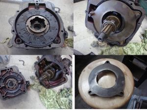
I know there was a whole tech bulletin published that was devoted to the Stewart Warner Power Brake unit but at the moment I can’t find it. We used it to put Ken Muellner’s ’33 back together. The discs can be rebuilt with Kevlar linings at Fort Wayne Clutch.
Bill
Jim and Bill,
Thanks for the contributions. Jim your working in forward or reverse explains why the, lets call it the Bendix, will travel in both directions.
After I cleaned off the area around the speedo attachment, it is a 1 1/8″ hex nut to get it off and pull out the shaft. The gear is held on the splined shaft with a big flat snap ring. It doesn’t have holes for a normal snap ring tool so I will have to improvise I guess. I am thinking piston ring pliers and a lever or 2″
Try PAS Service Bulletins 1974-1 and 2004-6.
Dave,
Thanks, I have them on CD. I will check them out.
Bill
Next is the freewheeling unit. Six bolts, one is kind of hidden and you must remove the top filler plug to get one out. Case just slides off although clearance is tight.
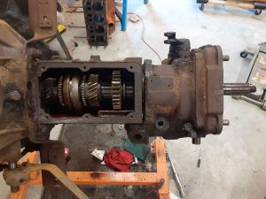
This is the output shaft from the transmission.
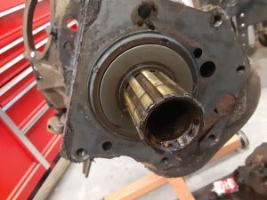
And this is the mating end of the freewheeling unit that slides into the end of the previous pic.
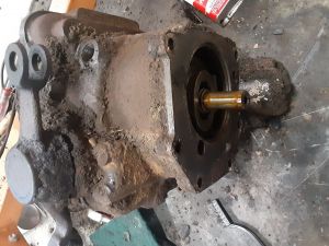
service bulletin 1974 #3 has dictator,commander and president transmission, tree wheeling and overdrive information on disassembly, operation and rebuilding. Based on 1935 models with the information applicable to PA transmissions 1932-38.
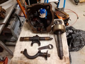
This is the end of the freewheeling that mates to the gearbox. Notable items are the hub in the center of the shaft has a shift fork on the right. It runs in a groove on the ring behind it. I moved the hub so you can see the fork.
To the right are 2 shafts that are connected and have to do with locking out or in the freewheeling.
If you look in the right upper corner, there is a square block with a hole in it. As it rotates it lifts a pin that blocks the movement of one of those shafts. It is the freewheeling cable attachment point. It rotates and rises as the cable is pulled out.
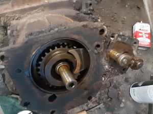
To finish disassembling the freewheeling section, Unbolt the spring lever arm from the lower shaft, replace with a longer bolt. Remove the double yoke that actuates the brake cables by removing the cotter pin secured pin and lift it off the shaft. There was a lot of play in this assembly.
Drive the shaft, using the inserted bolt, thru the splined fork and the case. Note alignment. Remove the fork and reassemble so you don’t forget the orientation. I can see nothing to do with these parts but clean and reinstall.
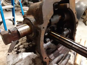
From this side you can see the seal and needle bearing that the shaft rides on. These may be a problem.
If you look below the hole you will see another shaft. It has a t2 bolt retainer that I removed to get to this point. To get this fork out you have to drive the bushing it rotates in from the inside of the case. Thad give you enough room to remove the fork.
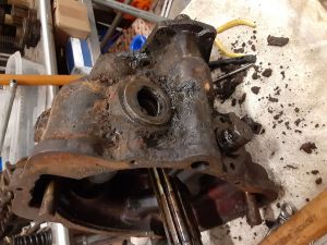
Here are the shaft/fork assemblies and the output/input shafts and there retainers along with the input shaft and selector gear.
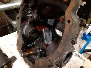
If you look inside the case you can see the selector fork that engages the gear
Here is a better picture of the caged roller bearing and the selector fork.
Remove the pinch bolt, it is piloted, which allows you to remove the freewheeling actuation lever/ It pulls out.
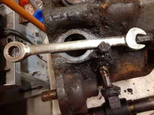
Remove the cover on the front of the case that covers the 2 actuation rods.
There is another elongated check pin between the rods so you have to have the detent on one lined up with the pin before you can pull the other.
Once one is out the other can be removed. The pin prevents both rods moving at the same time.
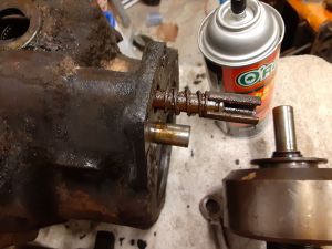
Lastly, to remove the shift fork you have to remove an Allen head set screw visible thru on of the top holes. Shaft pulls out and then you can remove the fork and spring. Don’t forget to remove the detent oval above. I used a magnet. Getting it back in will be tricky.
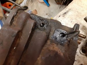
Starting on the brake case. I decided to clean it by hand which does a couple things, gives an opportunity to inspect thoroughly, you notice things like casting marks, part numbers, other details and it gives you a calming activity for listening to music, smoking a cigar or having a beer or cocktail.
I used Easy Off oven cleaner, no fume version in lemon scent to degrease everything. Spray it on, wait till it starts to show signs of the grease running, only a couple minutes, and wipe off with a paper/cloth towel. For the heavy deposits I used a couple of small flat and angled wood carving chisels and a dental pick.
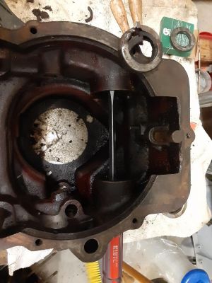
Next, to remove the brake yoke seals and bearing, I used a long screwdriver to drive them out coming the opposite side or from the inside out. Be sure to drive the bearing out using the rim of the bearing, for soon to be obvious reasons.
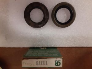
The parts list on this site identified the correct seals. I was able to source all but one of them, by those numbers.
The 50695/450695 I couldn’t find but it crossed over to a CR11776 for $11 on Ebait. Only difference is the depth is about half which may cause a problem with bearing retention.
I also found a common trailer bearing seal for a buck and change and it looks like it will work as it is a double seal but the ID is slightly larger. National 470706.
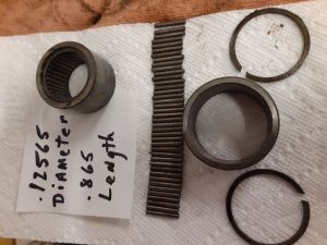
The top bearing is a made up component. The lower one is disassembled and shows the 40 rollers, housing and 2 snap rings.
You remove the snap rings and the .12565″ OD x .865″” long rollers fall out.
They all checked out ok and will be cleaned and reused.”
