- Home
- About Us
- Join/Renew
- Member Benefits
- Member Pages
- Log In
- Help
- Museum Store
Is the correct assemble sequence for the valve train in an 8 with hydraulic tappets
Thanks
Bill
I put the valves in before the tappets and blocks, it is a pain compressing the valves and getting the keepers in, harder if the tappets are in the way. The cam can be rotated to a no lift position for all 4 valves of each block. The blocks with tappets can be removed with the engine assembled, but a bit tricky to keep the followers from dropping out as you do it. I am already forgetting, but I think when assembling the blocks I angled the blocks in so the cam would keep them from falling out, then the tappet plungers could be depressed enough to roll the blocks into position. You might have to pull them in and out again if the allowed tappet clearance isn’t within spec – it is a very wide allowance though since they are hydraulic.
Thanks Jim. That is just what I was looking for and makes sense.
Jim is correct: Install the valves and springs, then the lifter blocks. It is important to have the lifters themselves dry inside. When the lifters have oil in them, you cannot compress them and you won’t get them between the cam lobes and the ends of the valve stems.
In the early Motors Manuals, there is about a page of info about the Hydraulic lifters and procedures. They suggest using gasoline to clean the lifters of oil and dirt [hopefully not much dirt!] and installing the lifters dry.
Bill it is also very important to make sure the gasket between the lifter block and the engine block is positioned correctly and not blocking the oil ports. The gaskets have too small of holes for the oil ports, and as such if the gasket is just a bit off location, the oil ports can be blocked..
Greg Long
I forgot to add: Make sure that you have some gap between the lifter plunger and the end of the valve stem.. Depending on your valves and how deep the seats in the block have been cut or ground it is possible to have no clearance when the lifter plunger is fully depressed and the cam lobe is down.. this would be a very extreme example of a valve overly ground and the seat very deeply cut into the cylinder block but it is possible..
Greg Long
Thanks Jim and Greg,
Happy New Year, by the way.
I bought an industrial ultrasonic cleaner and plan to use it on the tappet bodies.
Working on getting the rust/gunk out of all the oil passages.
I have 3 cam bearings in and am going to grind the valves next.
Hoping 2021 has less obstacles on all fronts.
Ultrasonic cleaner arrived today. Plugged it in and nothing happened. Hummm.
Took a panel off and found an unattached wire, plugged it in and off it went.
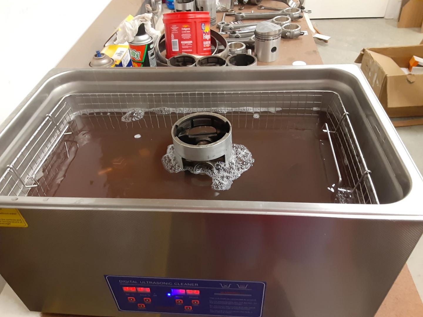
It is a 6 gallon and works with a variety of solvents. I am using Simple Green Concentrate I got at Home Depot. Makes about 13 gallons I think and is biodegradable. The solution gets dirty in a hurry. I got it basically to clean delicate parts but I think I will use it instead of my parts washer to clean greasy/oily parts. If you are trying to do rust removal you would need a different solution.
Seems well made for a Wuhan product. It has a digital heater and timer. Came with a basket and lid. 300 series Stainless it appears.
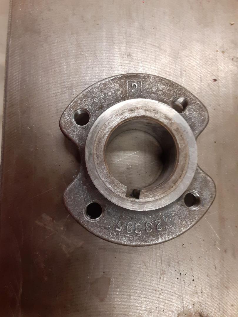
I put the cam retainer flange, which was very greasy, in for 10 min. Here is before
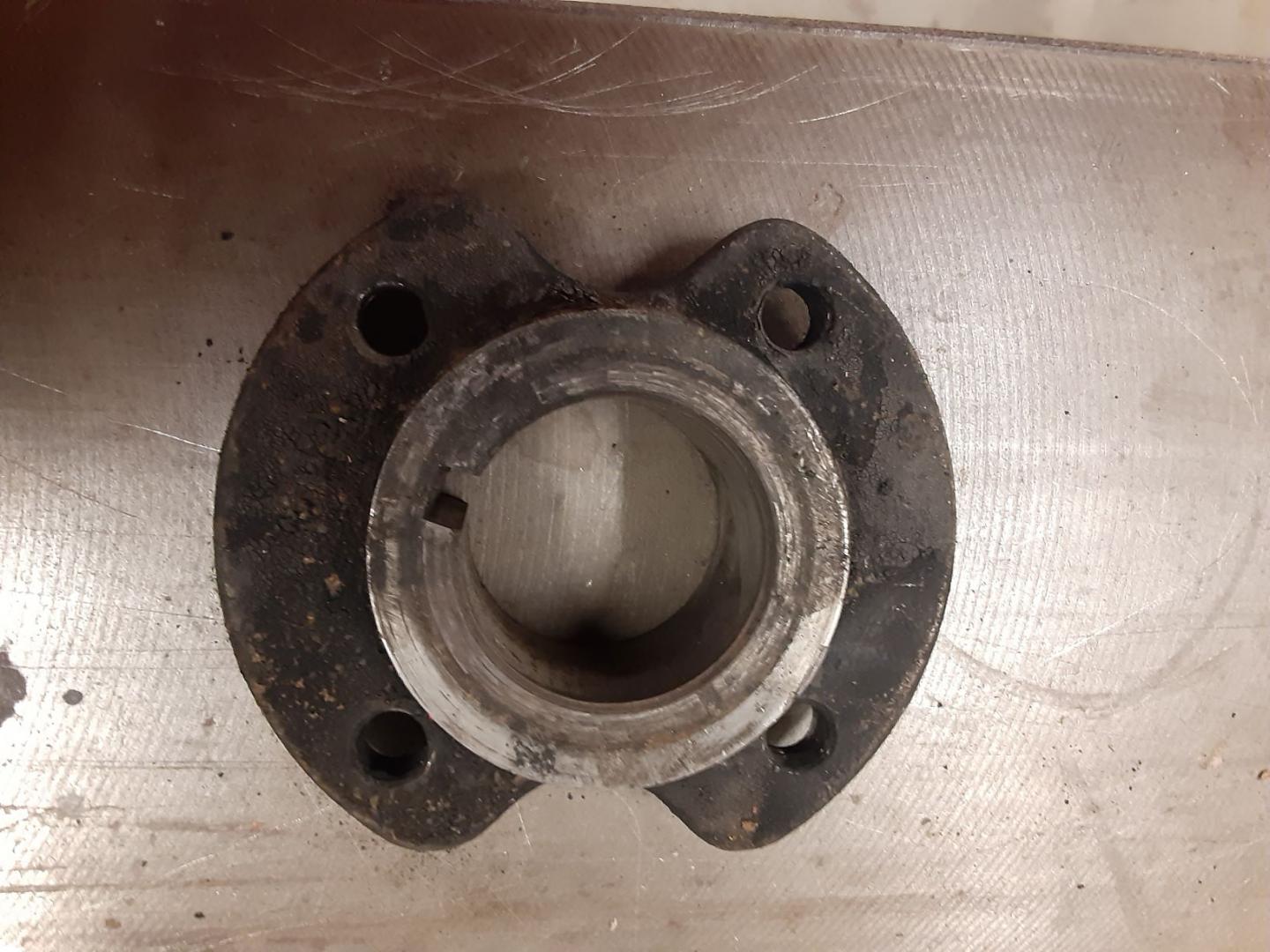
And here is the after. Probably could have left it in for longer. It does a great job of cleaning in threaded holes and bores. Might throw the tappets in later today. Even cleans around the casting numbers.
Here is a tappet block before. I punch marked the body (#4) and the rim of each tappet so I could keep them in their original bores.
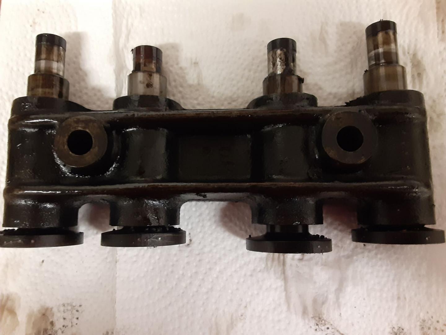
And after 30 min in the UC. Need more disassembly and time in the tank I guess. The oily looking areas on the bracket is just water. They are squeaky clean. Should have bought one of these when I got the car.
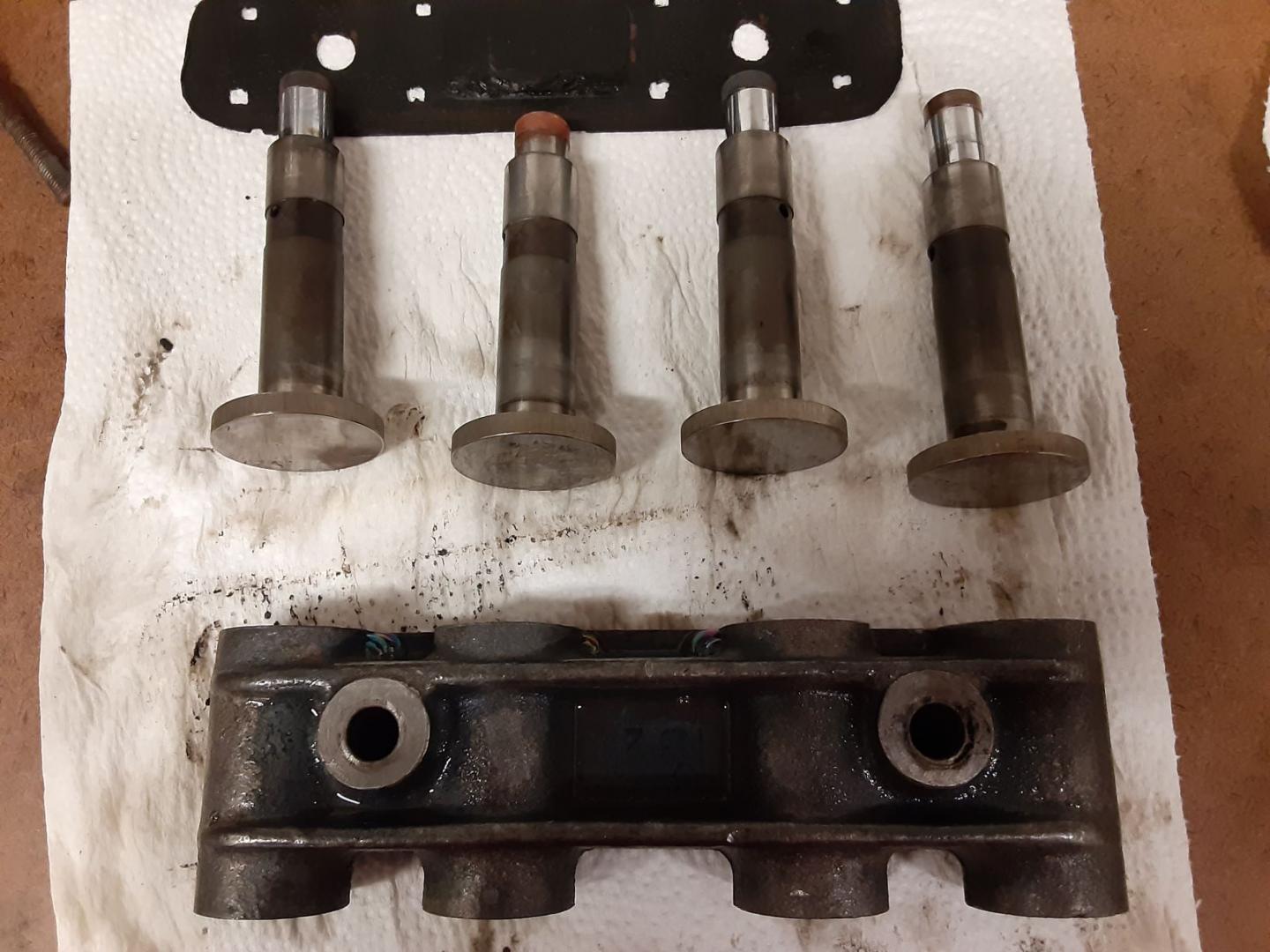
On the Ultrasonic cleaner, I have found out that it is important to rinse and dry the steel parts ASAP and I use a fogging oil on them.
They are so clean, they tend to get surface rust very quickly.
Back to the cam bearings.
I made this tool on my lathe out of aluminum. The cam bearings get progressively smaller, so I started with the front hole in the empty block and machined the drift to fit the bare hole with a shoulder at the top. Then I measured the id of the bearing and made a step so the drift just fit the id of the bearing, had a shoulder to sit on the rim of the bearing but would clear the block as the bearing was pushed out.
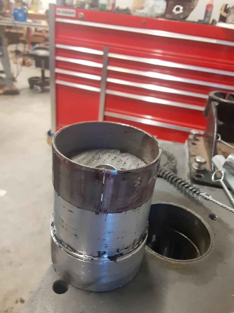
I center drilled it so I could use an all thread rod to pull it in, just in case I had problems driving them in.
Once out I inspected degreased and ultrasonically cleaned the shell. They are numbered and are of the split ring type and were in great shape.
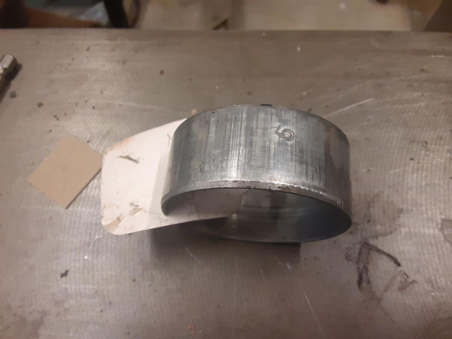
I used the same tool to reinsert them in the new block. Once one was in I repeated the measure and machining process to fit the next (smaller) hole.
5 down and 1 to go but I have to flip the block to get at the rear bearing and plug. Since the cam is thru drilled, bearings 2 thru 5 have no oil holes so there are no alignment issues.
Cam bearing are all out and was able to save the end plug. #6 cam bearing, which is the one at the rear has an oil hole that you have to line up but it is located at 9 o’clock looking forwards, not at 6.
I ordered a couple gun cleaning kits to clean out the oil galleries. The main one runs down the water jacket side of the block and feeds all the cam bearings. I had to order 2 kits to get enough of the treaded together rods to go the total length of the block. This kit is for 20 and 12 ga shotguns.

Here is the assembled rod laying on top of the block below the valves.
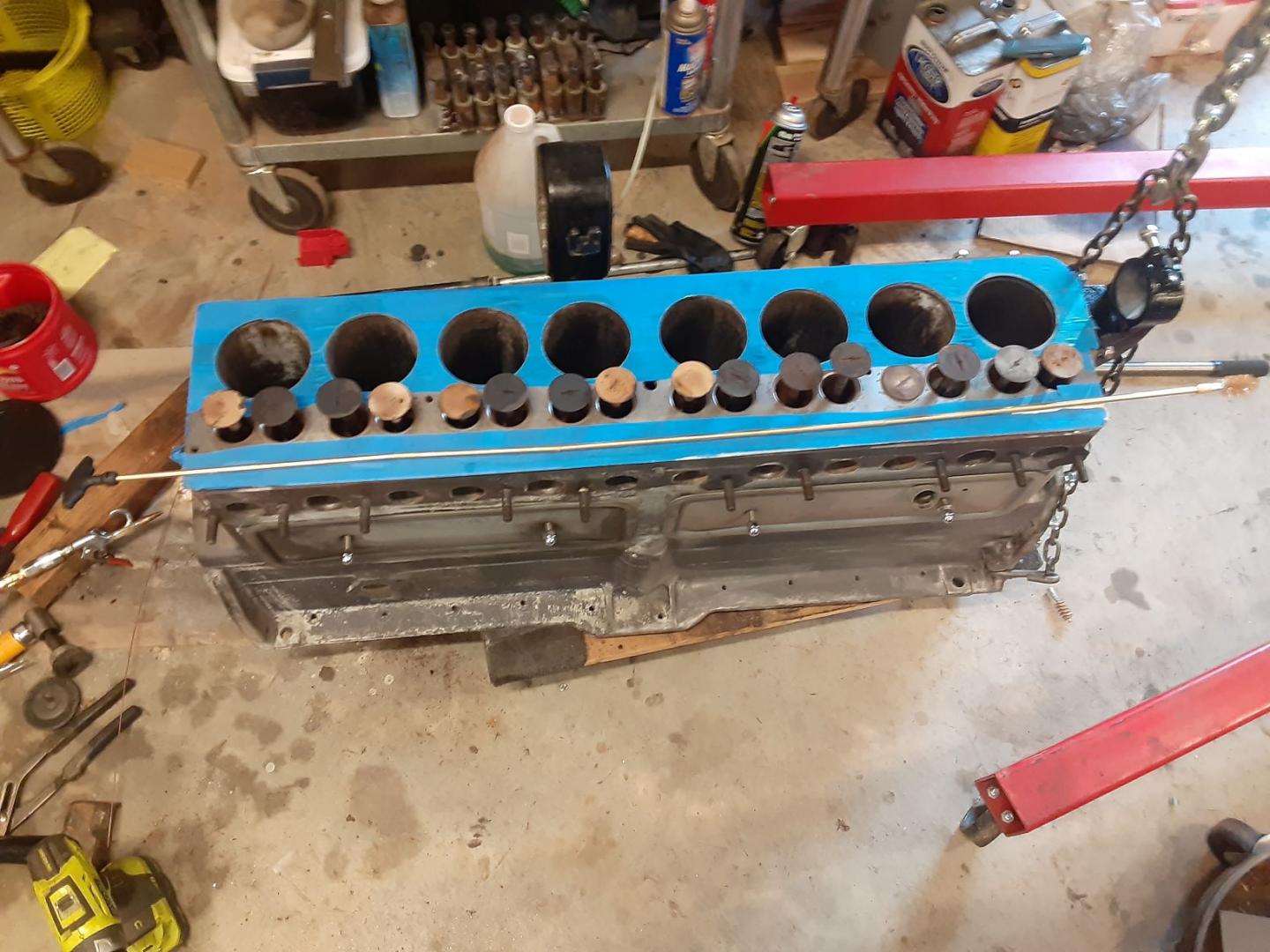
I started with the 20ga as it measured the closest to the galley bore. Then followed up with the 12ga. I got a lot of rusty dust and debris. This is the front of the gallery.

Rear of gallery
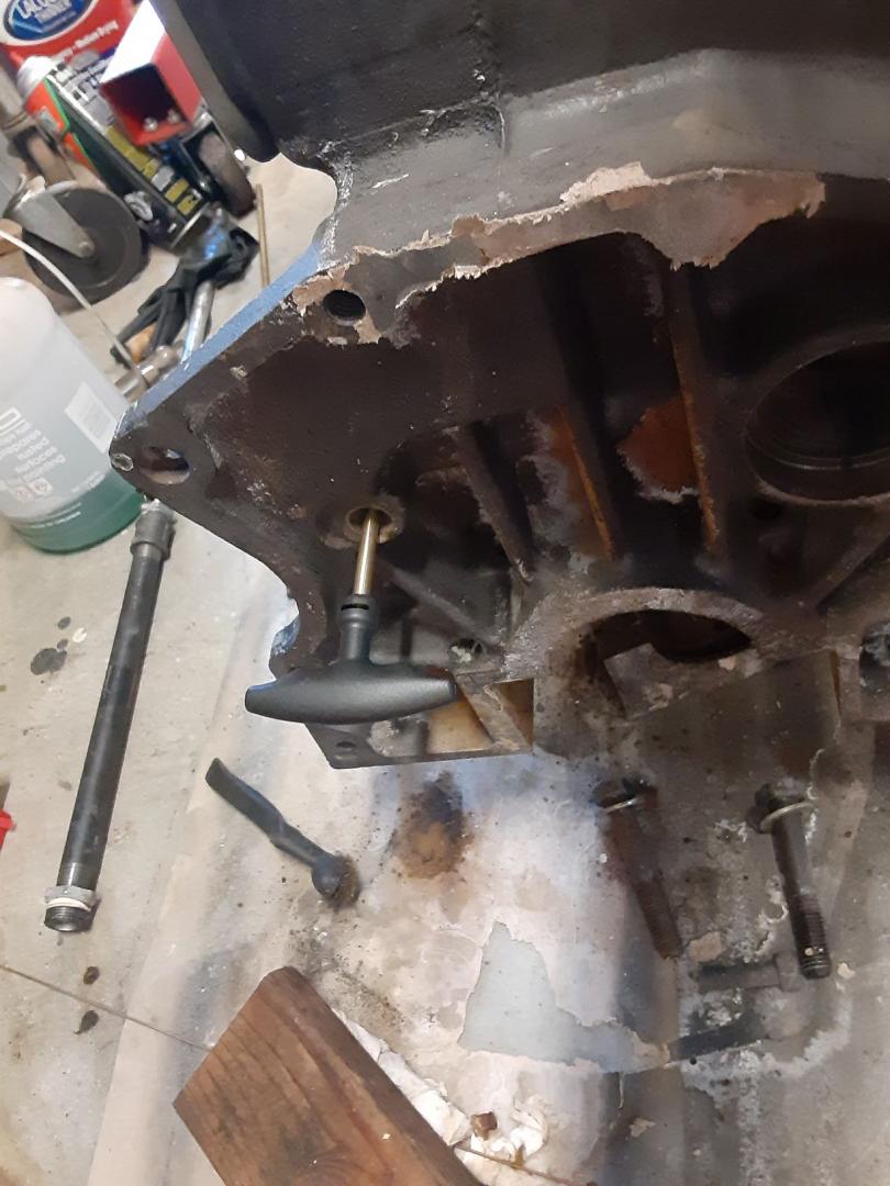
I will use the white swabs and use some sort of rust remover to get the gallery clean. Then I will run my endoscope down it to make sure there is nothing left.
Next is the side galleries that go to the bearings.
That will take a different brush, but the nice thing about gun cleaning brushes is they go from .17 or so on up so you can get a very close match to the gallery size.
Put #6 in, alignment was good. I was looking to get the channel from the oil gallery to the #6 cam bearing cleaned so I took off the right angle fitting at the back of the block and it was completely blocked as was the channel to the #6 cam journal. This block had been hot tanked the old way about 30+ years ago, but I had it retanked after it was surfaced. Notice the rust coming out of the block. That thing in my hand is the right angle fitting that I just took off the block. No oil going thru that baby. I had to drill thru all the junk blocking the gallery.
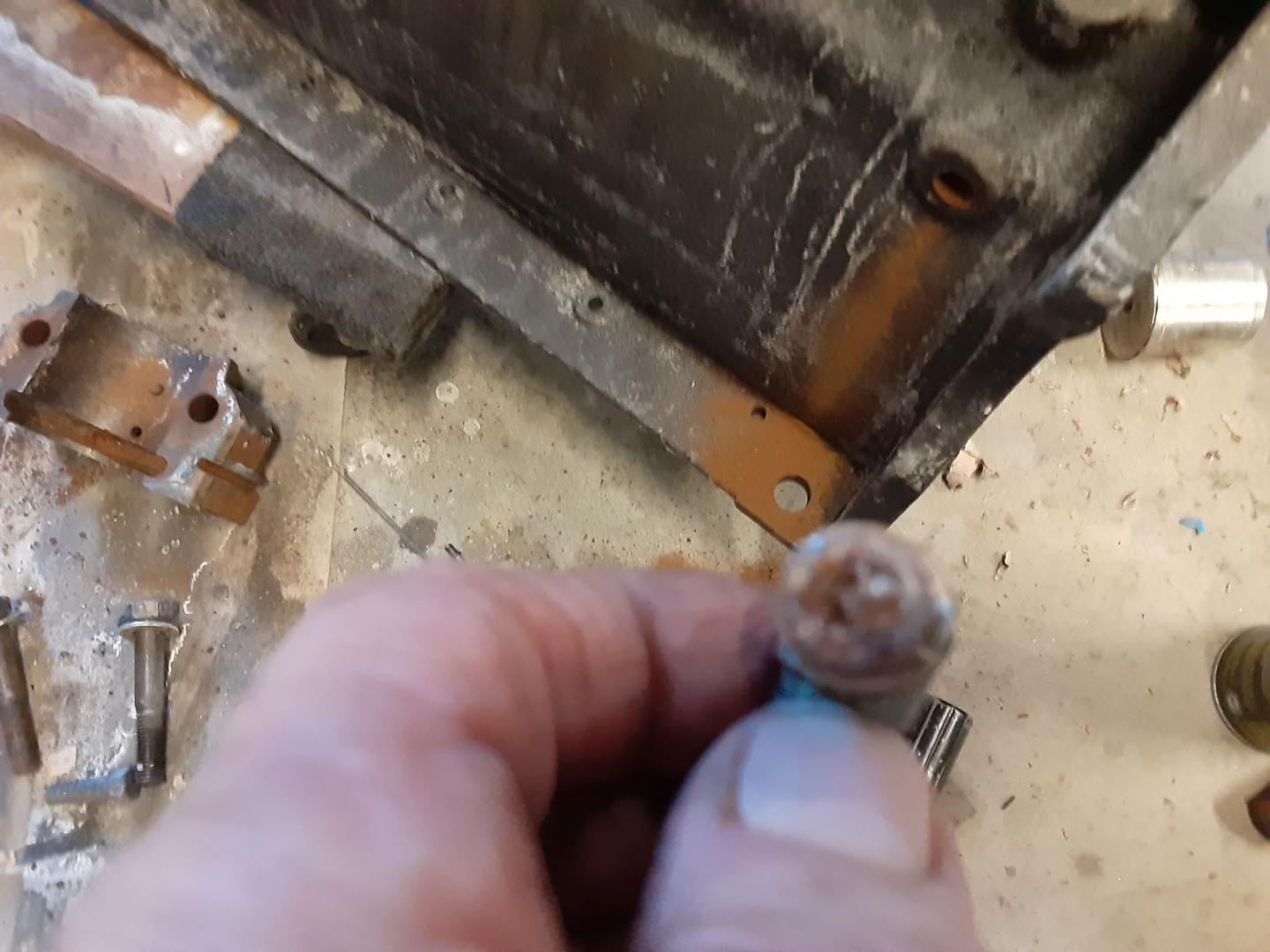
I guess the lesson is don’t trust that your galleries are good unless you personally check them. The channel to the cam bearing appears to be between 1/4 and 5/16 so I ordered a bore brush that will do .30 caliber up to 8 mm.
I have resisted trying to drill out the channels as they are long and if you broke a drill off in them, you are in for a struggle.
I have found the long drill bits tend to break easier than smaller ones.
Don’t ask me how I know.
I am sticking with the brushes and derusting solution.
Bill,
Thanks very much for your always excellent presentations.
Dave Stevens
Dave,
Thank you for the kind words. I enjoy hearing about people with operational cars, but for the moment I don’t have that.
I have bead blasted the valves. I have an assortment of PMC and Eaton valves and picked out the best from the ’33 and the ’35.
The ’33 has the lowest miles and I think the valves were the original PMC ones. All the Eaton ones came from the ’35 so I don’t know if that tells a story or not.
The interesting think about the valves is the slot in the head of them. It allows for a tool to be inserted to grind the valves.
The egg beater looking thing is a valve oscillator.
You put a light spring on the valve stem then insert the valve in the guide with grinding past on the face.
The spring allows you to lift the valve and redistribute the paste.
You insert the spade blade on the beater into the slot in the valve and start turning the handle.
It is geared so that as you turn the handle it automatically oscillates the valve clockwise then counter clockwise.
Saves having to use the sticks with rubber cups that you have to use the spinning between the hands fire starting skills from Boy Scout days.
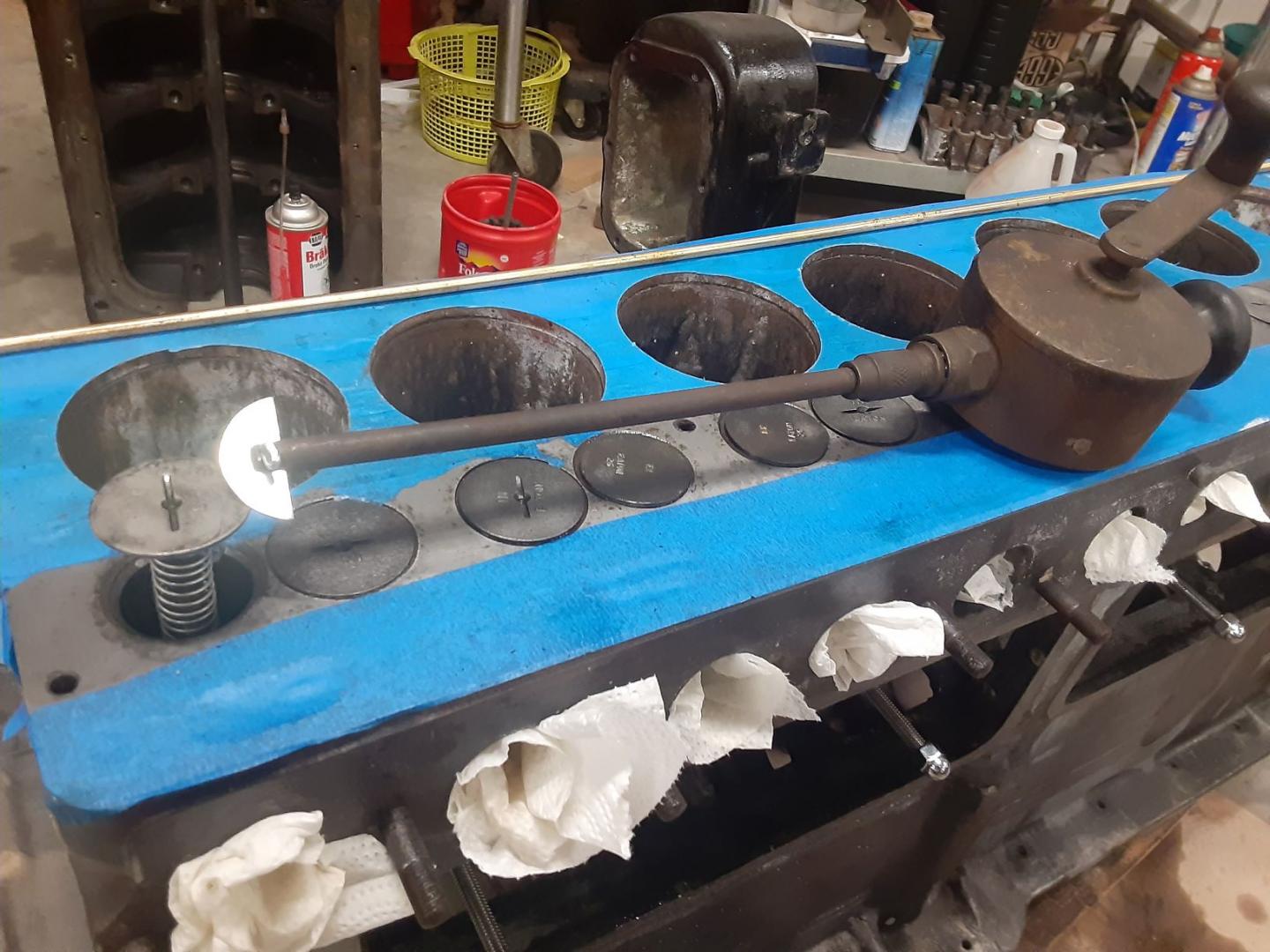
Still have a couple with out the slots that I will have to do the fire starting wafy.
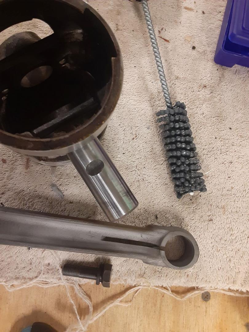
I have been struggling with getting the piston pins and pinch bolts installed in the rods. It is a push fit for the pin in the piston, but I couldn’t get the pin to turn in the rod so I could line up the notch machined in the pin that locks it to the rod with a bolt that “pinches” the pin on the rod. I tried heating the rod end and freezing the pin. By the time I got the pin in the one side of the piston, thru the rod, in the other side of the piston and tried to install the pinch bolt, things cooled or heated up to the extent it locked the pin in the rod.
I started to do some measurements. An old motor article which has just about all the clearances for just about anything on any car in the 30’s. It listed the PA pin at 15/16″.(.9375).
I mic’d mine at .9465. I then mic’d the bore of the rod and got .945 in the 3-9 o’clock axis and .947 in the 12-6 axis. Just enough to prevent turning the pin in the rod. Evidently the pinch bolt becomes oval when released. So close but so far.
I also had some burrs on the end of the pin hole so I bought a 15/16, 320 grit flex-hone and ran it thru the pin hole about 5 strokes and checked for pin fit. After about 3 cycles I was able to get a push fit on the pin and was able to rotate it. I assembled the pin, rod and piston and was able to rotate the pin so I could get the bolt in. Tightened it up and its ready do go.
I remember several years ago, my Dad had a similar problem. He boiled the pistons in a pot of water for awhile and the pins slid right in.
All the rods and pistons are assembled. I went back and measured the width of the slot in the rod.
At the big end side it measured .133″ and at the pin end measured .129. There goes your pin clearance.
I started cleaning out the smaller galleries. I started with a .25 caliber gun brush and that did nothing. Move up to a .30/.32 and that seems the correct size.
